- Links:
- A Pi Pico Oscilloscope
- RPScope
- ula
- scoppy
- logicanalyzer
- [Raspberry Pi Pico 200Khz Digital Oscilloscope](https://www.instructables.com Raspberry-Pi-Pico-200Khz-Digital-Oscilloscope/)
- picowi
- Picowi part 10: Web camera
- Scoppy
PIO相关
Links:
- Learn How To Access The Programmable I/O on the Raspberry Pi RP2040
- Learn how to Program and Debug Raspberry Pi Pico with SWD
- Pio-RP2040
- tinygo-org/pio
- RP2040 : PIO - case study
- Raspberry Pi pico PIO 初探
- Pico-PIO-USB
- Shift Registers – 74HC595 & 74HC165 with Arduino
- How 74HC595 Shift Register Works & Interface it with Arduino
- LCD parallel driver using Pico PIO
- Playing with the Pico Part 4 - Getting Acquainted with PIO
- Serial to Parallel Shifting-Out with a 74HC595
- Shift Registers – 74HC595 & 74HC165 with Arduino
- Not clear on how to use 2 non-consecutive GPIO’s in PIO
- 白話解密 Raspberry Pi Pico 的 PIO(Programmed I/O) — — 使用 MicroPython 撰寫 pioasm:Part I
Simple example to demonstrate
1 | .program squarewave |
OpenOCD烧写调试
1 | ~$ ../configure --enable-cmsis-dap --enable-sysfsgpio --enable-imx_gpio --enable-bcm2835gpio --enable-xds110 --enable-ftdi --enable-stlink |
- 添加支持
Pyua PY25Q32H nor flash的支持
1 | ~ openocd$ git diff |
- 烧写
1 | ~$ openocd -f interface/ftdi/ft232h-module-swd.cfg -f target/rp2040.cfg -c "program blink.elf verify reset exit" |
UF2文件方式烧写
pico-examples里的工程编译完成后,都会生成.uf2的文件,按住BOOTSEL上电进入到UF2模式,复制粘贴.uf2进去,就能烧写成功。或者使用
arduino-pico里的工具烧写,如下:
1 | python3 -I /home/michael/.arduino15/packages/rp2040/hardware/rp2040/3.6.2/tools/uf2conv.py --serial /dev/ttyACM0 --family RP2040 --deploy /tmp/arduino_build_788465/shift.ino.uf2 |
学习理解tinyusb+pico-sdk编译工程结构
- TinyUSB is an open-source cross-platform USB Host/Device stack for embedded system, designed to be memory-safe with no dynamic allocation and thread-safe with all interrupt events are deferred then handled in the non-ISR task function.
1 | ~$ git clone https://github.com/hathach/tinyusb |
- 下面以
tinyusb/examples/device/cdc_msc的工程为例。
1 | tinyusb/examples/device/cdc_msc$ tree |
- 分析
CMakeLists.txt文件
1 | tinyusb/examples/device/cdc_msc$ cat -n CMakeLists.txt |
- 上面的
CMakeLists.txt第4行引入其它的tinyusb/hw/bsp/family_support.cmake文件,如下:
1 | tinyusb/hw/bsp$ cat family_support.cmake |
ta
TinyUSB是一个嵌入式系统下开源跨平台的USB协议栈,以RP2040为例,它的开发实现是要依赖于pico-sdk的。编译工程
1 | ~ examples/device/video_capture$ mkdir build && cd build |
使用TFT_eSPI(ardion)驱动ili9341 16bit并口屏
安装rp2040 bsp支持
- 安装第三方的arduino-pico库,让
Arduino IDE可以支持rp2040板子。 - 首先在
Arduino IDE -> File -> Preference -> Additional Boards Manager URLs:添加下面的链接:
1 | https://github.com/earlephilhower/arduino-pico/releases/download/global/package_rp2040_index.json |
- 再打开
Board Manager进行联网更新,搜索pico并且安装Raspberry Pi Pico/RP2040的包。
配置TFT_eSPI
打开已经预定义好的文件:
~/Arduino/libraries/TFT_eSPI/User_Setups/Setup107_RP2040_ILI9341_16bit_parallel.h,把屏幕与RP2040按照文件的线序进行连接。再打开
~/Arduino/libraries/TFT_eSPI/User_Setups/User_Setup_Select.h,只打开上面这一个文件的注释。
1 | #include <User_Setups/Setup107_RP2040_ILI9341_16bit_parallel.h> |
- 选择打开一个
TFT_eSPI内置的测试工程。这里使用的是官方的板子,就选择Tools -> Boards -> Rasperry Pi RP2040 Boards -> Rasperry Pi Pico. 编译上传就可以看到结果,烧写过程中有可能需要手动复位BOOTSEL按键。
双74HC565N Daisy-chaining测试
| RP2040 | 74HC565N(1) | 74HC565N(2) | Logic Probe |
|---|---|---|---|
| GPIO0 | STCP | STCP | |
| GPIO1 | SHCP | SHCP | |
| GPIO2 | DS | ||
| VCC | VCC | VCC | |
| VCC | MR | MR | |
| GND | GND | GND | |
| GND | QE | QE | |
| Q7S | DS | ||
| Q0 | D00 | ||
| Q1 | D01 | ||
| Q2 | D02 | ||
| Q3 | D03 | ||
| Q4 | D04 | ||
| Q5 | D05 | ||
| Q6 | D06 | ||
| Q7 | D07 | ||
| Q0 | D08 | ||
| Q1 | D09 | ||
| Q2 | D10 | ||
| Q3 | D11 | ||
| Q4 | D12 | ||
| Q5 | D13 | ||
| Q6 | D14 | ||
| Q7 | D15 |
- 按照上面表格接连,在
Arduino里烧写下面的测试代码。
1 | int latchPin = 0; // Latch pin of 74HC595 is connected to Digital pin 5 STCP storage clock pin |
- 如果使用逻辑分析仪抓取到
parallel协议解析出来也是aa=0xf3,就是工作正常的。
使用pico-sdk驱动双屏
这里使用
GPIOs bit-banging的方式驱动两个ILI9341的屏幕:- 一个是
3.2 inch 320x240 16bit Parallel接口。 - 一个是
2.8 inch 320x240 SPI接口。
- 一个是
由于
16bit Parallel LCD会需要16个以上的GPIO大部分板子比较难支持到,这里尝试使用两个74HC595N串连(Daisy-chaining)起来,达到(Serial Input Parallel Output)效果来驱动屏幕。测试线路连接如下表所示。
| RP2040 | 74HC565N(1) | 74HC565N(2) | 3.2 inch 16bit | 2.8 inch SPI |
|---|---|---|---|---|
| GPIO0 | DS | SDI(MOSI) | ||
| GPIO1 | SHCP | SHCP | SCK | |
| GPIO2 | RS | DC | ||
| GPIO3 | WR | |||
| GPIO4 | RESET | RESET | ||
| GPIO5 | STCP | STCP | ||
| VCC | VCC | VCC | ||
| VCC | MR | MR | ||
| GND | GND | GND | GND | GND |
| GND | QE | QE | ||
| Q7S | DS | |||
| Q0 | D00 | |||
| Q1 | D01 | |||
| Q2 | D02 | |||
| Q3 | D03 | |||
| Q4 | D04 | |||
| Q5 | D05 | |||
| Q6 | D06 | |||
| Q7 | D07 | |||
| Q0 | D08 | |||
| Q1 | D09 | |||
| Q2 | D10 | |||
| Q3 | D11 | |||
| Q4 | D12 | |||
| Q5 | D13 | |||
| Q6 | D14 | |||
| Q7 | D15 | |||
| VCC | VCC | VCC | VCC | VCC |
| VCC | BL(High Act) | |||
| VCC | RD | |||
| GND | CS | CS | ||
| GND | BL(Low Active) |
- 使用的初始寄存器的参数如下,发现初始化的命有顺序的限制,比如:
0xf7不跟在0xe8后面,会出现屏幕无法显示的结果.
1 | static const uint8_t st7789_init_seq[] = { |
- 最终使用
GPIOs bit-banging shiftout(位移)的核心代码如下:
1 | #define LSBFIRST 0 |
- 上面的代码可以同时驱动两块不一样接口的屏幕,但是速度非常的慢,类似一种灯箱广告加载的效果,主要是因为在
shiftout里面有三处使用了sleep_us(1)导致的。但是这个地方不用sleep_us(1),3.2 inch 16bit就无法显示, 且使用__asm volatile("nop\n");都无法替代sleep_us(1).如果只是驱动SPI的LCD,去掉sleep_us(1),屏幕会流畅的刷新。
简单逻辑分析仪示例
- Install Rust
1 | ~$ rustup target add thumbv6m-none-eabi |
- 连机编译与烧写运行
1 | ~$ git clone https://github.com/dotcypress/ula |
- Hold the BOOTSEL button while connecting your board to the computer, then run following command.
1 | ~$ cd ula |
PulseView
- Select Openbench Logic Sniffer & SUMP compatible protocol when connecting to μLA.
SigrokCli
- Scan for devices
1 | ~$ sigrok-cli -d ols:conn=/dev/tty.usbmodem_ula_1 --scan |
- Sample two 10 MHz square waves with 90° phase shift
1 | ~$ sigrok-cli -d ols:conn=/dev/tty.usbmodem_ula_1 |
LoRa通信
- Links:
USB协议栈
USB结构简介
- Links:

Descriptor Types
The most commonly used descriptors include:
- Device Descriptor
- Configuration Descriptor
- Interface Descriptor
- Endpoint Descriptor
- String Descriptor
Every USB device must have one Device Descriptor and at least one each of the Configuration, Interface, and Endpoint Descriptors.
Device Descriptor
- The Device Descriptor is the first descriptor read by the Host during enumeration. The purpose of the Device Descriptor is to let the Host know what specification of USB the device complies with and how many possible configurations are available on the device. Upon successful processing of the Device Descriptor, the Host will read all the Configuration Descriptors.
Configuration Descriptor
A device may have more than one configuration. Each device configuration is assigned a number. The Configuration Descriptor serves two purposes:
Informs the Host as to how many interfaces (i.e., virtual devices) are in the configuration. While it is common for a configuration to offer only one interface, Devices that appear like two or more products have more than one interface.
How much power the device will consume if this configuration is activated by the Host. If the device is capable of controlling its power consumption, it may offer more than one configuration. Each configuration will advertise how much power would be consumed if the configuration were to be activated.
Interface Descriptor
An Interface Descriptor describes the details of the function of the product. Key elements include the number of endpoints on the device and which USB device class is implemented by the endpoints. For example, if the device were a keyboard, the specified device class would be Human Interface Device (HID) and the number of endpoints would be two.
Endpoint Descriptor
- Each endpoint on a device has its own descriptor. The descriptor provides the endpoint address (i.e., endpoint number), the size of the endpoint, and the data transfer type used to access the endpoint.
- Endpoint 0 (EP0IN and EP0OUT) are reserved in every device for control purposes.
- A USB device can have up to 32 endpoints (16 OUT and 16 IN). Since EP0IN and EP0OUT are set aside as control endpoints, the maximum number of endpoints available to transmit application data is 30.
String Descriptor
- Strings Descriptors are optional human readable strings which the Host OS may display.
1 | ~$ lsusb -v -s 001:005 |
USB Transfer Types
| Desc | Interrupt Transfers | Isochronous Transfers | Bulk Transfers |
|---|---|---|---|
| Benefits | High-reliability data transfers with a fixed response time | High bandwidth | High reliability with the potential for high bandwidth |
| Drawback | Bandwidth may be limited (64 KBytes for Full-Speed USB) | No CRC hardware. If a CRC is needed it must be done in software. Long packets can limit the number of devices being enumerated. | Bandwidth may vary depending upon the number of interrupt endpoints enumerated and the activity of enumerated Isochronous endpoints. |
| Typical Use | Mice, Keyboards, and Medical Devices | Audio/Video streaming, serial port emulation | Mass Storage and Printers |
| Notes | Up to 90 percent of the frame can be allocated for Interrupt endpoints.The maximum length of the transfer depends upon the frame size used. | Up to 90 percent of the frame can be allocated for interrupt endpoints. When not in use the bandwidth used will be released. The maximum length of the transfer depends upon the frame size used. | Will take advantage of unused Isochronous bandwidth.The maximum length of the transfer depends upon the frame size used. |
Linux USB手抓包分析
1 | ~$ lsmod | grep "usbmon" |
- 这里测试需要监听的要目标设备,是
TinyUSB的设备,在Bus 3, Device 90,
1 | ~$ lsusb | grep "TinyUSB" |
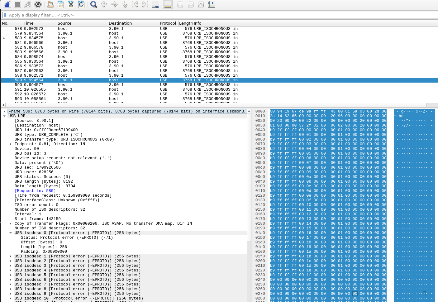
- 打开
wireshark, 选择usbmon3开始抓包。如下图所示,这里抓到的是错误码的UVC的包。
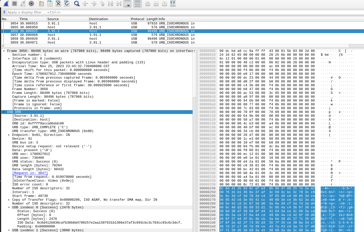
- 下面示例抓取一个正常的
UVC的协议包。在Bus 3, Device 91,
1 | ~$ lsusb | grep "EM-Camera" |
UVC相关
- Links:
MicroPython
下载安装MicroPython的固件
Download the correct MicroPython UF2 file for your board:
- Raspberry Pi Pico
- Raspberry Pi Pico W with Wi-Fi and Bluetooth LE support
Then go ahead and:
- Push and hold the BOOTSEL button and plug your Pico into the USB port of your Raspberry Pi or other computer. Release the BOOTSEL button after your Pico is connected.
- It will mount as a Mass Storage Device called RPI-RP2.
- Drag and drop the MicroPython UF2 file onto the RPI-RP2 volume. Your Pico will reboot. You are now running MicroPython.
- You can access the REPL via USB Serial.
通过USB访问UART串口
- 可以使用
minicom,也可以使用mpremote这里推荐使用后者。
1 | ~$ pip install mpremote |
测试ULN2003步进电机驱动
电机驱动板与
RP2040的连接
| RP2040 | ULN2003 |
|---|---|
| GPIO2 | IN1 |
| GPIO3 | IN2 |
| GPIO4 | IN3 |
| GPIO5 | IN4 |
| GND | GND |
| VUSB | +5V |
- 使用
minicom -o -b 115200 -D /dev/ttyACM0连接到RP2040的REPL命令行终端,输入以下的代码:
1 | import time |
- 也可以把上面的代码保存成文件如:
test_stepper_motor.py,使用mpremote运行:
1 | ~$ mpremote run test_stepper_motor.py |
测试Pico-W WIFI
- 先要确保存
Pico-W安装正确的固件Raspberry Pi Pico W,才能进行下面的测试。
1 | ~$ cat test_wifi.py |
- 使用
mpremote运行
1 | ~$ mpremote run test_wifi.py |
测试ILI9341+XPT2046
1 | ~$ git clone https://github.com/rdagger/micropython-ili9341 |
- 上传依赖文件到
rp2040,设置好正确接线。
1 | ~$ cd micropython-ili9341 |
- 创建测试代码
1 | ~ micropython-ili9341$ cat demo_touch.py |
测试使用lv_micropython
Build Instructions
1 | ~$ git clone https://github.com/lvgl/lv_micropython.git |
- Write firmware to device
1 | ~ lv_micropython$ cp ports/rp2/build-PICO/firmware.uf2 /media/michael/RPI-RP2/ |
CC1101
- Links: