参考:
Atmel AVR系列是一种基于改进的哈佛结构、8位~32位精简指令集(Reduced Instruction Set Computing,RISC)的微控制器,由Atmel公司于1996年研发.AVR系列是首次采用闪存(Flash Memory)作为数据存储介质的单芯片微控制器之一,同时代的其它微控制器多采用一次写入可编程ROM、EPROM或是EEPROM.目前AVR处理器发展了六个系列,分别是:tinyAVR,ATtiny系列;megaAVR,ATmega系列;XMEGA,ATxmega系列;Application-specific AVR,面向特殊应用的AVR系列,增加LCD控制器、USB控制器、PWM等特性;FPSLIC,FPGA上的AVR核;AVR32,32位AVR系列,包含SIMD和DSP以及音视频处理特性,与ARM架构形成争.
ATmega32U4(Arduino pro micro)
连接
ICSP烧写bootloader.1
2
3
4
5
6
7
8
9
10
11
12
13
14
15
16
17
18
19
20
21
22
23
24
25
26
27
28(2232HIO)
FT232H ATmega32U4
pin13 ADBUS0 <------> SCK pin15
pin14 ADBUS1 <------> MOSI pin16
pin15 ADBUS2 <------> MISO pin14
pin16 ADBUS3 <------> Reset RST
GND <------> GND
+3.3V <------> +3.3V
~$ avrdude -C /etc/avrdude.conf -c UM232H -P /dev/ttyUSB0 -b 19200 -p atmega32u4 -U lfuse:r:-:i
avrdude: AVR device initialized and ready to accept instructions
Reading | ################################################## | 100% 0.01s
avrdude: Device signature = 0x1e9587 (probably m32u4)
avrdude: reading lfuse memory:
Reading | ################################################## | 100% 0.00s
avrdude: writing output file "<stdout>"
:01000000FF00
:00000001FF
avrdude: safemode: Fuses OK (E:CB, H:D8, L:FF)
avrdude done. Thank you.some of valid programmers for FTDI
1 | 2232HIO = FT2232H based generic programmer |
- 添加sparkfun/Arduino_Boards,让
Arduino IDE支持更多的种类的板子,添加URL后,通过Tools -> Boards Manager安装SparkFun AVR Boards.烧写SparkFun bootloader.
1 | ~$ avrdude -C /etc/avrdude.conf -c UM232H -P /dev/ttyUSB0 -b 19200 -p m32u4 -U flash:w:.arduino15/packages/SparkFun/hardware/avr/1.1.13/bootloaders/caterina/Caterina-promicro16.hex |
ATmega328p (Arduino Pro mini with CH340)
- 烧写好
bootloader就可以使用USB在Arduino IDE上进行开发. - 选择
Tools -> Board -> Arduino Pro or Pro Mini, 烧写器AVRISP mkii.
UART通信的要点
不像其他的通讯协议,
UART沒有clock信号可供参考,所以双方需要事先知道彼此的baud rate,才知道双方是以多快的速度传送数据,必须条件:- 两个硬件设备必须要共
地(GND) Baud rate必须相同。
- 两个硬件设备必须要共
Baud rate为9600,每个bit的时间应该是1/9600秒,对于CPU来说是几个cycle呢?如果CPU频率是9600Hz,这样刚好就是1 cycle传输一个bit.
ATtiny85(CJMCU)
- Links:
- ATTiny10IDE
- [Tutorial : How to program the CJMCU ATTiny85 (LilyTiny / LilyPad)](https://diyprojects.io/ tutorial-program-cjmcu-attiny85-lilytiny-lilypad/)
- Digispark DIY: the Smallest USB Arduino
- Tiny AVR Programmer Hookup Guide
- Arduino / AVR #
- Little Wire
- ATtiny85 I2C protocol tutorial
- ATtiny85 Snake Game Handheld
- MiniCore
Bootloader
micronucleus是一个可以支持跨平台的
USB上传烧写的bootloader,体积在2kb以内.1
2
3
4
5
6
7
8
9
10
11
FT232H ATTiny85
pin13 ADBUS0 <------> SCK PB2
pin14 ADBUS1 <------> MOSI PB0
pin15 ADBUS2 <------> MISO PB1
pin16 ADBUS3 <------> Reset PB5
GND <------> GND
+5V <------> +5V
~ micronucleus/firmware/releases$ avrdude -C /etc/avrdude.conf -c UM232H -P /dev/ttyUSB1 -b 19200 -p attiny85 -U flash:w:t85_default.hex -U lfuse:w:0xe2:m -U hfuse:w:0xdd:m -U efuse:w:0xfe:m接入
USB会发现如下的设备:
1 | ~$ lsusb |
- 复制
micronucleus/commandline/49-micronucleus.rules到系统的/etc/udev/rules.d/目录内.
系统控制与复位
- 这里要讲到关于
熔丝位(fuse)的技术.具体的技术细节需要查看Datasheet的20. Memory Programming.可以根据文档去配置编程使能相应的字节的位.也可以通过这个https://www.engbedded.com/fusecalc/配置得出三个字节去配置熔丝位.lfuse表示低位,hfuse表示高位,efuse表示扩展位. - 在配置编程熔丝位时有几个问题要注意,比如:把
SPIEN,JTAGEN的位设定为未编程状态,这将使芯片失去了JTAG与SPI接口的功能,不能重新烧写,从而以致单片机锁死,出现这种情况时就需要高压(12v)并行编程方式才能将单片机的功能恢复.另一个问题是要启动地址的错误,如果没有开启单片机的BOOTLOADER功能,就不要设置BOOTRST的编程位为0(已编程),否则单片机在上电时不是从Flash的0x0000开始运行的,而是转到BOOT区执行,从而导致单片机无法正确运行.
使用Arduino IDE支持(ATTinyCore)
- ATTinyCore是让最新的
Arduino IDE支持ATTiny系列的单片机,安装流程当然也就是按照https://github.com/SpenceKonde/ATTinyCore/blob/master/Installation.md操作,在Arduino IDE -> File->Preferences加入http://drazzy.com/package_drazzy.com_index.json,并且更新安装ATTinyCore的库.之后在``Arduino IDE -> Tools -> Board -> ATTinyCore`里面可以选择目标的单片机. - 有可能
ATTinyCore自带的micronucleus版本太低与Attiny85内烧写版本的不匹配,就会出现下面的错误,具体的版本可以查看~/.arduino15/packages/ATTinyCore/tools/micronucleus/2.0a4/.关于ATTinyCore所支持的硬件与固件配置可以查看~/.arduino15/packages/ATTinyCore/hardware/avr/1.4.1/bootloaders.
1 | Warning: device with unknown new version of Micronucleus detected. |
- 关于上面的警告提示,需要更新
micronucleus版本.1
2~$ cd micronucleus/commandline && make
~$ cp micronucleus ~/.arduino15/packages/ATTinyCore/tools/micronucleus/2.0a4/
使用Arduino上传第一个程序(blink).
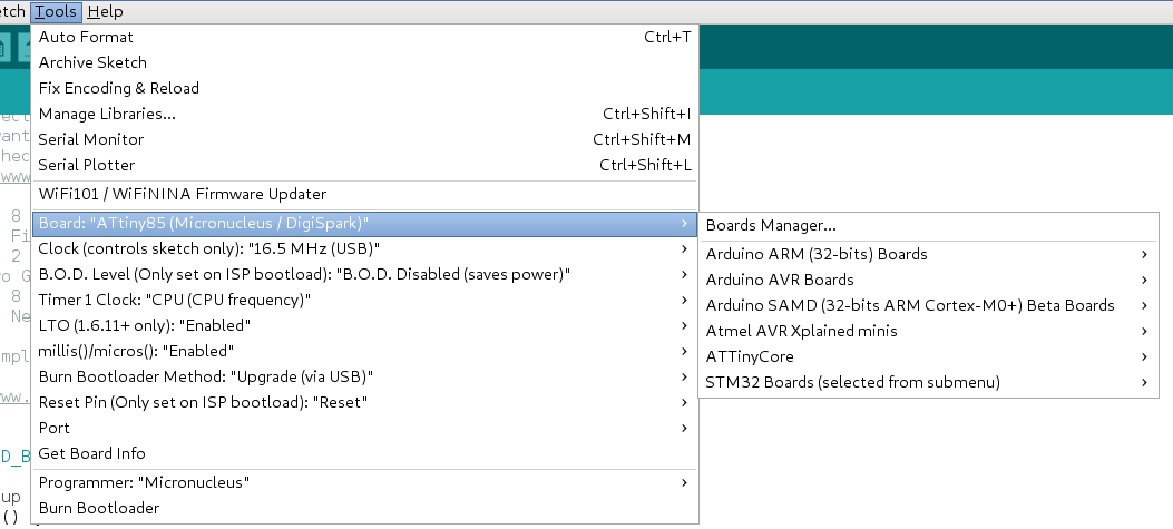
选择主板:
Tools -> Board -> ATTinyCore -> ATtiny85(Micronucleus/DigiSpark)烧写方式:
Tools -> Burn Bootloader Method: "Upgrade (via USB)"基本上选择了正确的主板,其它参数默认就可以了,测试图如下:
测式程序是:
File -> Examples -> Built-in examples -> 01.Basics -> Blink. 只是重定义了LED_BUILTIN的IO口,如下:1
2
3
4
5
6
7
8
9
10
11
12
13
14
15#define LED_BUILTIN 1
// the setup function runs once when you press reset or power the board
void setup() {
// initialize digital pin LED_BUILTIN as an output.
pinMode(LED_BUILTIN, OUTPUT);
}
// the loop function runs over and over again forever
void loop() {
digitalWrite(LED_BUILTIN, HIGH); // turn the LED on (HIGH is the voltage level)
delay(1000); // wait for a second
digitalWrite(LED_BUILTIN, LOW); // turn the LED off by making the voltage LOW
delay(1000); // wait for a second
}烧写提示如下:
1 | Plug in device now... (will timeout in 60 seconds) |
新增烧写器(UM232H为例)
-
1
2
3
4
5
6
7
8
9
10
11
12
13
14
15
16
17
18~$ tree -L 2 ~/.arduino15/packages/
/home/michael/.arduino15/packages/
├── arduino
│ ├── hardware
│ └── tools
├── atmel-avr-xminis
│ └── hardware
├── ATTinyCore
│ ├── hardware
│ └── tools
├── esp32
│ ├── hardware
│ └── tools
├── SparkFun
│ └── hardware
└── STM32
├── hardware
└── tools 在
~/.arduino15/packages/内的各种包内结构如下,基本每一个包(package: i.e: ardunion,ATTinyCore )下面的hardware\<arch>\<version\内都有boards.txt,programmers.txt文件.而在包下面的
hardware\tools\内包内,包含这个包所支持的工具链,如:编译器,烧写器,还有一些特定的工具等.这里以avrdude为例,在Arduino IDE烧写AVR的板子时候,它会调用包内的avrdude与配置文件,如:
1 | .arduino15/packages/arduino/tools/avrdude/6.3.0-arduino17/bin/avrdude \ |
- 下面是让
ATTinyCore包内的Attiny85通过使用UM232H烧写器,在Arduino IDE内烧写,无需其它的bootloader支持. - 首先在
~/.arduino15/packages/ATTinyCore/hardware/avr/1.4.1/programmers.txt内,加入以下内容:
1 | um232h.name=UM232H as ISP |
重启
Arduino IDE会发现,选择ATTinyCore包类的板子,在烧写器一栏,会看到UM232H as ISP. 如果在某个包类没有在定义programmers.txt,它就会使用目标板子在arduino体系内所对应~/.arduino15/packages/arduino/hardware/<arch>/<version>/programmers.txt如:
1
~$ .arduino15/packages/arduino/tools/avrdude/6.3.0-arduino17/bin/avrdude -C .arduino15/packages/ATTinyCore/hardware/avr/1.4.1/avrdude.conf
如果这里的
.arduino15/packages/ATTinyCore/hardware/avr/1.4.1/avrdude.conf文件内没有支持UM232H配置,需要在avrdude.conf加入下面内容:1
2
3
4
5
6
7
8
9
10
11
12
13
14
15
16
17
18
19
20
21
22
23
24
25
26
27
28
29
30# UM232H module from FTDI and Glyn.com.au.
# See helix.air.net.au for detailed usage information.
# J1: Connect pin 2 and 3 for USB power.
# J2: Connect pin 2 and 3 for USB power.
# J2: Pin 7 is SCK
# : Pin 8 is MOSI
# : Pin 9 is MISO
# : Pin 11 is RST
# : Pin 6 is ground
# Use the -b flag to set the SPI clock rate eg -b 3750000 is the fastest I could get
# a 16MHz Atmega1280 to program reliably. The 232H is conveniently 5V tolerant.
programmer
id = "UM232H";
desc = "FT232H based module from FTDI and Glyn.com.au";
type = "avrftdi";
usbvid = 0x0403;
# Note: This PID is reserved for generic 232H devices and
# should be programmed into the EEPROM
usbpid = 0x6014;
usbdev = "A";
usbvendor = "";
usbproduct = "";
usbsn = "";
#ISP-signals
sck = 0;
mosi = 1;
miso = 2;
reset = 3;
;如在运行烧写时出现在下面错误,也就是在一些
avrdude.conf内没有支持UM232H的原因之一.1
avrdude: Error: no libftdi or libusb support. Install libftdi1/libusb-1.0 or libftdi/libusb and run configure/make again.
这里比较简单解决办法是,使用系统的
/usr/bin/avrdude来替换.arduino15/packages/arduino/tools/avrdude/6.3.0-arduino17/bin/avrdude为什么
Arduino IDE为会调用包内的工具(avrdude),因为它的路径定义如下:1
2
3
4
5~$ grep "avrdude.path" ~/.arduino15/packages/arduino/hardware/avr/1.8.3/platform.txt
tools.avrdude.path={runtime.tools.avrdude.path}
~$ grep "avrdude.path" ~/.arduino15/packages/ATTinyCore/hardware/avr/1.4.1/platform.txt
tools.avrdude.path={runtime.tools.avrdude.path}最后,新增其它的种类的烧写器也是类似,如:
FT2232HL等.这种方式,就是可以使用Arduino IDE生态内的软件库,所带来快速开发与测试硬件的优势.也可使用Makefile的方式使用avrdude来烧写.
添加2232HL
- 打开
/etc/avrdude.conf文件发现,里面默认定义了FT2232H,FT4232H的配置如下:
1 | ~$ cat /etc/avrdude.conf |
- 如上所示,在系统级的
avrdude已经支持FT2232H,这里只需要硬件库里programmers.txt添加一个对应到FT2232H的项就可以了。但是一般在硬件库里,还有一份avrdude.conf,按顺序会先是检查硬件库里的相关配置。这里还是以ATTinyCore的硬件库为例:
1 | ~$ tail -n 10 ~/.arduino15/packages/ATTinyCore/hardware/avr/1.5.2/programmers.txt |
ft2232h连接attiny85
1 | FT2232H ATTiny85 |
AVRDude烧写
前面是在
ATTiny85Flash里烧写一个bootloader开启SELFPRGEN Self-Programming Enable与SPIEN Enable Serial Program and Data Downloading的功能,优点就是让它能通过USB(D-: PB3/AD3,D+: PB4/AD2)可以烧写程序,可以简单与Arduino IDE集成使用,不需要外接烧写器.缺点就是要消耗2kb的存储空间,但是Attiny85就只有8kb的Flash空间.下面就是通过使用
UM232H像烧写bootloader的方法去开发编程,可以完全使用8kb的空间.下面是一个简单blink示例.1
2
3
4
5
6
7
8
9
10
11
12
13
14
15
16
17
18
19
20
21
22
23
24
25
26
27
28
29
30
31
32
33
34
35
36~ blink$ cat main.c
// main.c
//
// A simple blinky program for ATtiny85
// Connect red LED at pin 2 (PB1)
//
// electronut.in
int main (void)
{
// set PB1 to be output
DDRB = 0b00000010;
while (1) {
// flash# 1:
// set PB1 high
PORTB = 0b00000010;
_delay_ms(20);
// set PB1 low
PORTB = 0b00000000;
_delay_ms(20);
// flash# 2:
// set PB1 high
PORTB = 0b00000010;
_delay_ms(200);
// set PB1 low
PORTB = 0b00000000;
_delay_ms(200);
}
return 1;
}Makefile
1
2
3
4
5
6
7
8
9
10
11
12
13
14
15
16
17
18
19
20
21
22
23
24
25
26
27
28
29
30
31
32
33
34
35
36
37
38
39
40
41
42
43
44
45
46
47
48
49
50
51
52
53
54
55
56
57
58
59
60# Makefile for programming the ATtiny85
# modified the one generated by CrossPack
DEVICE = attiny85
CLOCK = 8000000
PROGRAMMER = -c UM232H
OBJECTS = main.o
# for ATTiny85
# see http://www.engbedded.com/fusecalc/
FUSES = -U lfuse:w:0x62:m -U hfuse:w:0xdf:m -U efuse:w:0xff:m
# Tune the lines below only if you know what you are doing:
AVRDUDE = avrdude $(PROGRAMMER) -p $(DEVICE)
COMPILE = avr-gcc -Wall -Os -DF_CPU=$(CLOCK) -mmcu=$(DEVICE)
# symbolic targets:
all: main.hex
.c.o:
$(COMPILE) -c $< -o $@
.S.o:
$(COMPILE) -x assembler-with-cpp -c $< -o $@
.c.s:
$(COMPILE) -S $< -o $@
flash: all
$(AVRDUDE) -U flash:w:main.hex:i
fuse:
$(AVRDUDE) $(FUSES)
# Xcode uses the Makefile targets "", "clean" and "install"
install: flash fuse
# if you use a bootloader, change the command below appropriately:
load: all
bootloadHID main.hex
clean:
rm -f main.hex main.elf $(OBJECTS)
# file targets:
main.elf: $(OBJECTS)
$(COMPILE) -o main.elf $(OBJECTS)
main.hex: main.elf
rm -f main.hex
avr-objcopy -j .text -j .data -O ihex main.elf main.hex
avr-size --format=avr --mcu=$(DEVICE) main.elf
# If you have an EEPROM section, you must also create a hex file for the
# EEPROM and add it to the "flash" target.
# Targets for code debugging and analysis:
disasm: main.elf
avr-objdump -d main.elf
cpp:
$(COMPILE) -E main.c接线按照上面方法,因为这里是没有用使用
bootloader,直接在blink目录下运行make flash就通过使用avrdude烧写到flash中.也可以单独使用下面命令烧写.
1
~$ avrdude -C /etc/avrdude.conf -c UM232H -P /dev/ttyUSB1 -b 19200 -p attiny85 -U flash:w:main.hex:i
高压编程恢复熔丝位(fuse)锁死
Links
恢复
熔丝位(fuse)还是有一点麻烦,按照博文High Voltage programming/Unbricking for Attiny指导,需要有一个Arduino设备,或者说至少要一个有6个IO口的单片机.还需要6个1k的电阻,一个(npn)的三极管,一个12V的电压源.如图: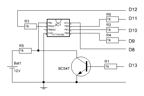
读取
熔丝位(fuse)1
2
3
4
5
6
7
8
9
10
11
12
13
14
15
16
17
18
19
20
21
22
23
24
25
26
27
28
29
30
31
32
33
34
35
36
37
38
39
40
41
42
43
44
45
46
47
48
49
50
51
52
53
54
55
56
57
58
59
60
61
62
63
64
65
66
67
68~$ avrdude -C /etc/avrdude.conf -c UM232H -P /dev/ttyUSB1 -b 19200 -p attiny85 -U lfuse:r:-:i -v
avrdude: Version 6.3-20171130
Copyright (c) 2000-2005 Brian Dean, http://www.bdmicro.com/
Copyright (c) 2007-2014 Joerg Wunsch
System wide configuration file is "/etc/avrdude.conf"
User configuration file is "/home/michael/.avrduderc"
User configuration file does not exist or is not a regular file, skipping
Using Port : /dev/ttyUSB1
Using Programmer : UM232H
Overriding Baud Rate : 19200
AVR Part : ATtiny85
Chip Erase delay : 4500 us
PAGEL : P00
BS2 : P00
RESET disposition : possible i/o
RETRY pulse : SCK
serial program mode : yes
parallel program mode : yes
Timeout : 200
StabDelay : 100
CmdexeDelay : 25
SyncLoops : 32
ByteDelay : 0
PollIndex : 3
PollValue : 0x53
Memory Detail :
Block Poll Page Polled
Memory Type Mode Delay Size Indx Paged Size Size #Pages MinW MaxW ReadBack
----------- ---- ----- ----- ---- ------ ------ ---- ------ ----- ----- ---------
eeprom 65 6 4 0 no 512 4 0 4000 4500 0xff 0xff
flash 65 6 32 0 yes 8192 64 128 4500 4500 0xff 0xff
signature 0 0 0 0 no 3 0 0 0 0 0x00 0x00
lock 0 0 0 0 no 1 0 0 9000 9000 0x00 0x00
lfuse 0 0 0 0 no 1 0 0 9000 9000 0x00 0x00
hfuse 0 0 0 0 no 1 0 0 9000 9000 0x00 0x00
efuse 0 0 0 0 no 1 0 0 9000 9000 0x00 0x00
calibration 0 0 0 0 no 1 0 0 0 0 0x00 0x00
Programmer Type : avrftdi
Description : FT232H based module from FTDI and Glyn.com.au
avrdude: AVR device initialized and ready to accept instructions
Reading | ################################################## | 100% 0.01s
avrdude: Device signature = 0x1e930b (probably t85)
avrdude: safemode: lfuse reads as 62
avrdude: safemode: hfuse reads as DF
avrdude: safemode: efuse reads as FE
avrdude: reading lfuse memory:
Reading | ################################################## | 100% 0.00s
avrdude: writing output file "<stdout>"
:01000000629D
:00000001FF
avrdude: safemode: lfuse reads as 62
avrdude: safemode: hfuse reads as DF
avrdude: safemode: efuse reads as FE
avrdude: safemode: Fuses OK (E:FE, H:DF, L:62)
avrdude done. Thank you.内存爆掉的问题,定义了一个
1024的数组.1
2
3
4
5
6
7
8
9
10
11avr-size --format=avr --mcu=attiny85 main.elf
AVR Memory Usage
----------------
Device: attiny85
Program: 2454 bytes (30.0% Full)
(.text + .data + .bootloader)
Data: 1043 bytes (203.7% Full)
(.data + .bss + .noinit)
ATTiny85/Atmega328p时钟计数器相关
- Links:
8位定时器(timer0)
- 先确认手上的
ATtiny85的时钟频是否在运行在8MHz,可以通过读取它的fuse位来判定,这里使用的是-U lfuse:w:0xe2:m -U hfuse:w:0xdf:m -U efuse:w:0xff:m.这里测试用的fuse配置如图
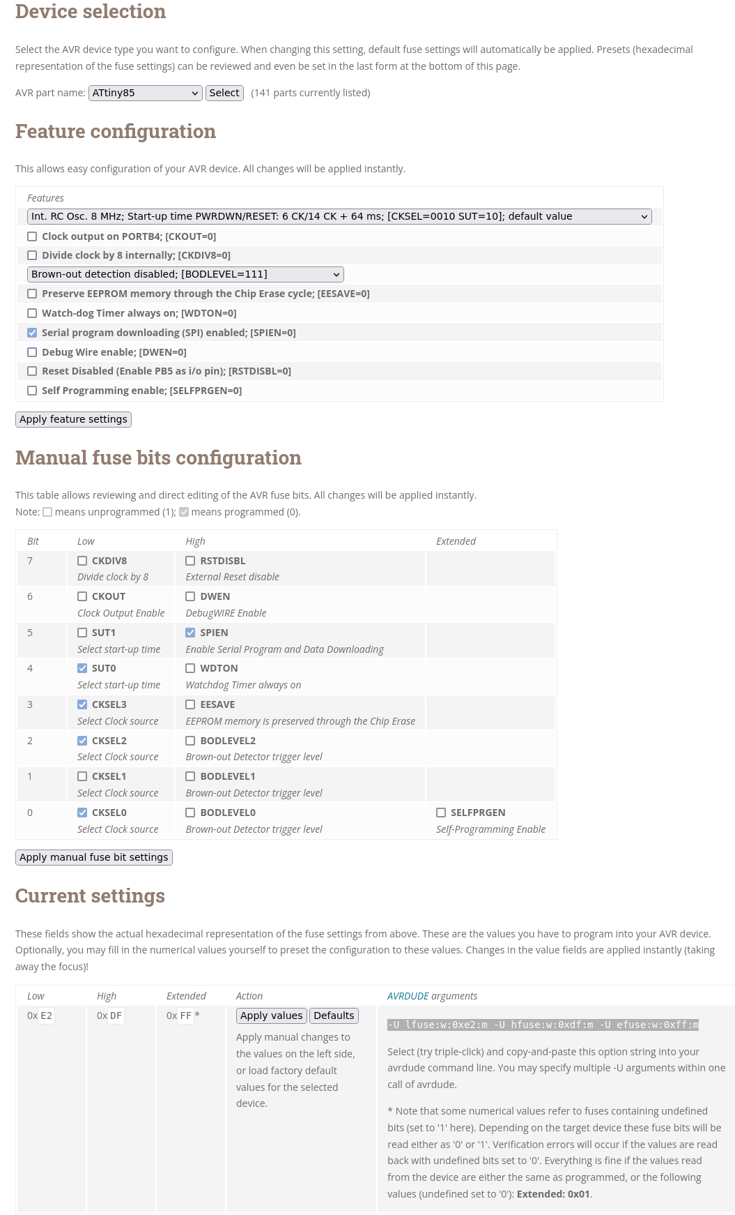
ATTiny85默认时钟频率是8MHz,表示它可以每秒进行8000000次周期开关(高电平,低电平),每一个周期的时间段(time period)是1/8000000s也就是0.000000125s,也就是125ns,而一个16位的定时器(0-65535),在每个时钟周期加一,从0到上65536上溢只需要8.192ms,8位的定时器只需要0.032ms就上溢了。如果我们需要更长时间的定时间隔,那么就需要预分频器对时钟进行分频处理,根据芯片手册14.9.2 TCCR0B - Timer/Counter Control Register B描述,通过设置TCCRB0B寄存器的Bit2:0位,可以进如下预分频
| CS02 | CS01 | CS00 | Description |
|---|---|---|---|
| 0 | 0 | 0 | No clock source (Timer/Counter stopped) |
| 0 | 0 | 1 | clk I/O /(no prescaling) |
| 0 | 1 | 0 | clk I/O /8 (from prescaler) |
| 0 | 1 | 1 | clk I/O /64 (from prescaler) |
| 1 | 0 | 0 | clk I/O /256 (from prescaler) |
| 1 | 0 | 1 | clk I/O /1024 (from prescaler) |
| 1 | 1 | 0 | External clock source on T0 pin. Clock on falling edge. |
| 1 | 1 | 1 | External clock source on T0 pin. Clock on rising edge. |
下面这个程序使用8位定时器来延时1秒,每秒翻转一次状态的
blink示例。ATtiny85默认是8MHz,每个周期是1/8MHz = 0.125us = 125ns,按1024预频后得到7812.5Hz。也就是说,定时器每隔7812.5Hz加1,换算成时间是1/7812.5 = 0.000128s,8位定时器只能计数到0.000128s * 255 = 0.032639999999999995。设定
T/C0的工作状态为CTC模式,开启T/C0输出比较匹配中断使能位,使用OCR0A比较寄存器保存数值做比较。这里设置OCR0A=250,当TCNT0的值达到250后就会产生比较中断(250 < 255>).中断32次后,也是就约等于1秒钟,并且对PB1的状态进行翻转。1
2
3
4
5
6
7
8
9
10
11
12
13
14
15
16
17
18
19
20
21
22
23
24
25
26
27
28
29
30
31
32
33
34
35
36
37~$ cat timer0.c
int intr_count = 0;
void setupTimer0() {
cli();
// Clear registers
TCCR0A = 0;
TCCR0B = 0;
// 7812.5 Hz (8000000/((0+1)*1024))
OCR0A = 250; // 0.000128s * 250 = 32ms
// CTC 比较匹配时清零定时器模式
TCCR0A |= (1 << WGM01);
// Prescaler 1024
TCCR0B |= (1 << CS02) | (1 << CS00);
// Output Compare Match A Interrupt Enable
TIMSK |= (1 << OCIE0A);
sei(); //enabling global interrupt, or SREG |= 0x80
}
ISR(TIMER0_COMPA_vect) {
if(intr_count == 31)
{
intr_count = 0;
PORTB^=(1<<PB1); //toggling the LED
} else intr_count++;
}
int main ()
{
DDRB = 0b00000010; // enable PB1
setupTimer0();
while(1)
{}
}ATtiny85的timer1也是一个8bit定时器,但是支持最大14-bit(MAX=16384)的预分频,下面是一个测试。设置比较寄存器的值为248,中断两次逻辑采样得到1.006s的方波。1/488.28125 = 0.002048s,也等于0.000000125s * 16384 = 0.002048s.
1 | ~$ cat timer1.c |
16位定时器(timer1)
- 下面这个程序使用
ATmega328p的16位定时器1来延时1秒,ATmega328p默认是16MHz,每个周期是1/16MHz = 0.0625us,把它1024的预分频后得到15625Hz,这里的设置与上面ATtiny85雷同,只是这里使用的是16位定时器(0-65535), 下面把比较器设置成15640通过逻辑采样得到一个1s的方波,而使用15625得到是0.9993s的方波。
1 | ~$ cat timer1.ino |
ATmega8-16PU
Link:
下面是使用一块
ATmega8-16PU与一块面包板,搭的简单测试
添加Arduino IDE支持
open
Filemenu, click onPreferences.Now inAdditional Boards Manger URLs, enter the following URL:https://mcudude.github.io/MiniCore/package_MCUdude_MiniCore_index.jsonGo to Tools menu and then select
Board > Boards Manager,In Boards Manager window, search forMiniCoreand then install the latest version.
ATmega8-16pu连接UM232H
1 | UM232H ATmega8-16pu arduino pin out |
读写fuse
下面是读取它的
fuse设置。1
2
3
4
5
6
7
8
9
10
11
12
13
14
15
16
17
18
19
20
21
22
23
24
25
26
27
28
29
30
31
32
33
34
35
36
37
38
39
40
41
42
43
44
45
46
47
48
49
50
51
52
53
54
55
56
57
58
59
60
61
62
63
64~$ avrdude -c UM232H -P /dev/ttyUSB1 -b 19200 -p m8 -U lfuse:r:-:i -v
avrdude: Version 6.3-20171130
Copyright (c) 2000-2005 Brian Dean, http://www.bdmicro.com/
Copyright (c) 2007-2014 Joerg Wunsch
System wide configuration file is "/etc/avrdude.conf"
User configuration file is "/home/michael/.avrduderc"
User configuration file does not exist or is not a regular file, skipping
Using Port : /dev/ttyUSB1
Using Programmer : UM232H
Overriding Baud Rate : 19200
AVR Part : ATmega8
Chip Erase delay : 10000 us
PAGEL : PD7
BS2 : PC2
RESET disposition : dedicated
RETRY pulse : SCK
serial program mode : yes
parallel program mode : yes
Timeout : 200
StabDelay : 100
CmdexeDelay : 25
SyncLoops : 32
ByteDelay : 0
PollIndex : 3
PollValue : 0x53
Memory Detail :
Block Poll Page Polled
Memory Type Mode Delay Size Indx Paged Size Size #Pages MinW MaxW ReadBack
----------- ---- ----- ----- ---- ------ ------ ---- ------ ----- ----- ---------
eeprom 4 20 128 0 no 512 4 0 9000 9000 0xff 0xff
flash 33 10 64 0 yes 8192 64 128 4500 4500 0xff 0x00
lfuse 0 0 0 0 no 1 0 0 2000 2000 0x00 0x00
hfuse 0 0 0 0 no 1 0 0 2000 2000 0x00 0x00
lock 0 0 0 0 no 1 0 0 2000 2000 0x00 0x00
calibration 0 0 0 0 no 4 0 0 0 0 0x00 0x00
signature 0 0 0 0 no 3 0 0 0 0 0x00 0x00
Programmer Type : avrftdi
Description : FT232H based module from FTDI and Glyn.com.au
avrdude: AVR device initialized and ready to accept instructions
Reading | ################################################## | 100% 0.01s
avrdude: Device signature = 0x1e9307 (probably m8)
avrdude: safemode: lfuse reads as 62
avrdude: safemode: hfuse reads as DF
avrdude: reading lfuse memory:
Reading | ################################################## | 100% 0.00s
avrdude: writing output file "<stdout>"
:01000000629D
:00000001FF
avrdude: safemode: lfuse reads as 62
avrdude: safemode: hfuse reads as DF
avrdude: safemode: Fuses OK (E:FF, H:DF, L:62)
avrdude done. Thank you.写入
fuse的配置,这里是通过AVR® Fuse Calculator配置计算出来的。

1 | ~$avrdude -c UM232H -P /dev/ttyUSB1 -b 19200 -p m8 -U lfuse:w:0xd4:m -U hfuse:w:0xc9:m |
基于Rust语言开发测试
- Links:
Prerequistes
1 | ~$ sudo apt install binutils-avr avr-libc gcc-avr pkg-config avrdude libudev-dev |
Install Micronucleus (Optional)
ft2232hLink toLilytiny Attiny85
1 | FT2232H ATTiny85 |
- Build and Flash firmware
1 | ~$ git clone https://github.com/micronucleus/micronucleus |
- Build micronucleus flash CLI tool
1 | ~$ sudo apt-get install libusb-dev |
- Connected to board USB
1 | ~$ lsusb -v -s 001:030 |
Install Rust env
1 | ~$ cargo +stable install ravedude |
Build blink project
1 | ~$ git clone https://github.com/Rahix/avr-hal |
Build release Minimzing Rust Binary Size test
- added following lines into the
Cargo.toml
1 | [profile.release] |
- Build Release
1 | ~$ RUSTFLAGS="-Zlocation-detail=none" cargo build --release |
驱动NRF24l01
Links:
[nRF24l01 control with 2 MCU pins using time-division duplexed SPI](https://nerdralph.blogspot.com/2015/05/ nrf24l01-control-with-2-mcu-pins-using.html)
[ATtiny85 SPI protocol – Master and Slave mode tutorial](https://www.gadgetronicx.com/ attiny85-spi-protocol-master-slave-mode-tutorial/)
NRF24l01正常工作的要寄存器值如下:
1 | CONFIG: 0b |
驱动SSD1306
- Tiny Graphics Library
- ATtiny85 Graphics Display
- ATTiny85 – OLED (I2C)
- ATtiny-USI-I2C-Master
- TinyI2C Library
- lexus2k/ssd1306
- Send a single pulse low/high pulse then stay high
- OLED_Interface_With_8051
- Debugging SSD1306 Display Problems
调试
GDB
逻辑分析仪的问题
- Fx2lafw
- PulseView
- Use a raspberry pi pico (rp2040) as a logic
- Raspberry Pi PinOut
- 连接逻辑分析仪时,不知为何,有时会出现干扰,让程序跑飞,而断开后运行的很正常.
字符相关
- fontconverter
- Custom Fonts for Microcontrollers
- fontbm
- Making graphics and fonts for embedded systems
- fontbuilder
- LCD Character Set
AVR-GCC汇编相关
- AVR GCC assembler techniques
- Inline Assembler Cookbook
- Basic Assembly Language programming
- Introduction to AVR assembler programming for beginners
- MCUCR Detial
GCC asm Statement
Let’s start with a simple example of reading a value from port D:
1
asm("in %0, %1" : "=r" (value) : "I" (_SFR_IO_ADDR(PORTD)) );
Each
asmstatement is devided by colons into (up to) four parts:- The assembler instructions, defined as a single string constant:
"in %0, %1" - A list of output operands, separated by commas. Our example uses just one:
"=r" (value) - A comma separated list of input operands. Again our example uses one operand only:
"I" (_SFR_IO_ADDR(PORTD)) - Clobbered registers, left empty in our example.
- The assembler instructions, defined as a single string constant:
You can write assembler instructions in much the same way as you would write assembler programs. However, registers andconstants are used in a different way if they refer to expressions of your C program. The connection between registersand C operands is specified in the second and third part of the asm instruction, the list of input and output operands,respectively. The general form is
1 | asm(code : output operand list : input operand list [: clobber list]); |
- In the code section, operands are referenced by a percent sign followed by a single digit.
%0refers to the first%1tothe second operand and so forth. From the above example:
1 | %0 refers to "=r" (value) and |
Input and Output Operands
- Each input and output operand is described by a constraint string followed by a C expression in parantheses. AVR-GCC 3.3knows the following constraint characters:
- Note
- The most up-to-date and detailed information on contraints for the avr can be found in the gcc manual.
- The
xregister isr27:r26, theyregister isr29:r28, and thezregister isr31:r30
| Constraint | Used for | Range |
|---|---|---|
| a | Simple upper registers | r16 to r23 |
| b | Base pointer registers pairs | y, z |
| d | Upper register | r16 to r31 |
| e | Pointer register pairs | x, y, z |
| q | Stack pointer register | SPH:SPL |
| r | Any register | r0 to r31 |
| t | Temporary register | r0 |
| w | Special upper register pairs | r24, r26, r28, r30 |
| x | Pointer register pair X | x (r27:r26) |
| y | Pointer register pair Y | y (r29:r28) |
| z | Pointer register pair Z | z (r31:r30) |
| G | Floating point constant | 0.0 |
| I | 6-bit positive integer constant | 0 to 63 |
| J | 6-bit negative integer constant | -63 to 0 |
| K | Integer constant | 2 |
| L | Integer constant | 0 |
| l | Lower registers | r0 to r15 |
| M | 8-bit integer constant | 0 to 255 |
| N | Integer constant | -1 |
| O | Integer constant | 8, 16, 24 |
| P | Integer constant | 1 |
| Q | (GCC >= 4.2.x) A memory address based on Y or Z pointer with displacementa. | |
| R | (GCC >= 4.3.x) Integer constant. | -6 to 5 |
| Mnemonic | Constraints | Mnemonic | Constraints |
|---|---|---|---|
| adc | r,r | add | r,r |
| adiw | w,I | and | r,r |
| andi | d,M | asr | r |
| bclr | I | bld | r,I |
| brbc | I,label | brbs | I,label |
| bset | I | bst | r,I |
| cbi | I,I | cbr | d,I |
| com | r | cp | r,r |
| cpc | r,r | cpi | d,M |
| cpse | r,r | dec | r |
| elpm | t,z | eor | r,r |
| in | r,I | inc | r |
| ld | r,e | ldd | r,b |
| ldi | d,M | lds | r,label |
| lpm | t,z | lsl | r |
| lsr | r | mov | r,r |
| movw | r,r | mul | r,r |
| neg | r | or | r,r |
| ori | d,M | out | I,r |
| pop | r | push | r |
| rol | r | ror | r |
| sbc | r,r | sbci | d,M |
| sbi | I,I | sbic | I,I |
| sbiw | w,I | sbr | d,M |
| sbrc | r,I | sbrs | r,I |
| ser | d | st | e,r |
| std | b,r | sts | label,r |
| sub | r,r | subi | d,M |
| swap | r |
- Constraint characters may be prepended by a single constraint modifier. Contraints without a modifier specify read-only operands. Modifiers are:
- Modifier Specifies
1 | = Write-only operand, usually used for all output operands. |
comment In assembler programming, the term clobbered registers is used to denote any registers whose value may beoverwritten during the course of executing an instruction or procedure.
谢谢支持
- 微信二维码: